- Product techniques
- Skived fin heat sink
- Friction stir welded heat sink
- Heat pipe thermal module
- Water cooler
- Applications and industries
- Cooling solutions for electric car controllers
- Wind power converter cooling solution
- PV inverter cooling solution
- Energy storage system cooling solution
-

Official account

Official website


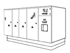 Via the excitation on the rotor of the doubly-fed induction wind generators, wind power converters are capable of making the amplitude, frequency, and the phase of the stator of the doubly-fed generator the same as the electrical grid. Depending on the requirements, it can also carry out the independent decoupling control of active or reactive power. Using converters to control the doubly-fed induction wind power generators can realize the soft cut-in control and reduce the adverse effects of the cut-in impulse current on the electric motor and electrical grid. In other words, whether a wind power converter operates stably will directly affect the stability of the electrical grid. In order to ensure the normal operation of the wind power converters, cooling is an indispensable and critical part.