3C products are also called information home appliances, which typically mean computers, telecommunications, and consumer electronics. There are a wide variety of products with a huge demand. China has become the worldwide largest 3C consumption market for 3C products. With the enhancement of the financial condition and income of our citizens, there is a higher demand for the quality of electronic products. Companies launch products with better configuration, better performance, andbetter designs in order to satisfy consumers
There are a great number of factors which affect the quality of electronic products and cooling is a factor that could not be neglected. Especially after the development of the "Samsung battery-gate" event in 2016, electronics manufacturers pay more attention to the cooling performance and safety of their products. How to make sure the cooling of an electronic product meet the stringent design requirements? The best approach is to plan for thermal management at the beginning of the product design cycle so as to acquire the optimal cooling solution. Winshare Thermal is an outstanding cooling techniques supplier, who can provide the cooling solutions for IT telecommunication electronics products including mainboard cooling, CPU cooling, graphics card cooling, radio frequency module cooling,RU cooling, game console cooling,VR cooling, IPC cooling, server cooling, central variable frequency air conditioner cooling,TEC cooling, etc.
The target to be achieved by the simulation of the cooling solution:
PCB source temperature |
≤100℃ |
CPU temperature |
≤80℃ |
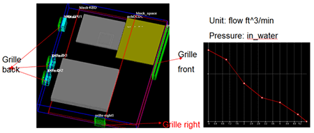
Schematic of simulation model and relevant parameters:
(1)
DCDC output
|
Thermal conductivity:10W/(m*K) Power:5W
|
CPU chipset
|
Thermal conductivity:10W/(m*k) Power:10W
|
PCB MST
|
Thermal conductivity:15W/(m*K) Power:5W
|
CPU PCB
|
Thermal conductivity:15W/(m*K) Power:4W
|
CPU heat sink
|
Dimensions: 125*95*6mm, base plate thickness:2mm, fin count: 10pcs, thickness: 0.6mm;Thermal conductivity: AL-extru. 180W/(m*K)
|
CU block
|
Dimensions:41*41*4.7, Thermal conductivity:385 W/(m*k)
|
Thermal grease
|
Thickness: 0.3mm,Thermal conductivity:3.5W/(m*K)
|
Soldering approach
|
Solder paste 4258,Thermal conductivity:48W/(m*k) 0.2mm
|
(2)
Front side of the grille
|
Dimensions:170*27mm; Open area ratio:0.5
|
Right side of the grille
|
Dimensions:35*30 mm; Open area ratio:0.6
|
Back side of the grille
|
Dimensions:30*30 mm; Open area ratio::0.7
|
fan
|
Dimensions:30*30*10 mm
|
(3)
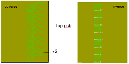
Top side of mainboard
|
Dimensions:140*170mm; Thermal conductivity:10W/(m*k); Power:3W
|
Back side of heat source
|
0.8W/pcs
|
Front side of heat source
|
Left row:0.8W/pcs; right row: 1.2W/pcs;
The Row marked as "2":1.5W/pcs
|
Heat sink
|
Dimensions:140*170*4.5mm; Base plate thickness: 2mm; Fin height:2.5mm,
Fin count:10pcs; fin thickness:0.6mm; Thermal conductivity:180W/(m*K)
|
Thermal grease
|
Thickness: 0.3mm; Thermal conductivity:3.5W/(m*K)
|
(4)
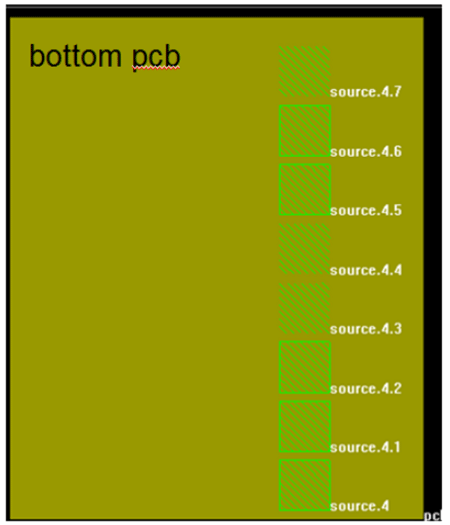
ottom side of mainboard
|
Dimensions:140*170mm; Thermal conductivity:10W/(m*k); Power:3W。
|
Source of inverse
|
功率:1.5W/pcs
|
Heat sink
|
Dimensions:140*170*4.5mm; Base plate thickness: 2mm; Fin height:2.5mm,
Fin count:10pcs; Fin thickness:0.6mm; Thermal conductivity:180W/(m*K)
|
Thermal grease
|
Thickness: 0.3mm; Thermal conductivity:3.5W/(m*K)
|
Descriptions of the heat sink cooling solution:
(1) Add an30*10mm axial fan to increase the air flow through RX module;
(2) Modify the copper fins in front of the fan in order to increase system air flow.
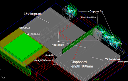
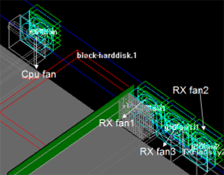
Schematic of the simulation model of the overall cooling layout:
Parameters of the copper fins after the modification:
Copper fins
|
Dimensions:30*12*0.3mm; Inclination: 1.0; Quantity: 30pcs
|
Material:C1100; Thermal conductivity:385W/(m*K)。
|
Heat pipe
|
D6 heat pipe thickness: 3mm with the pressed-tube technique; Heat pipe type: Powder sintered;
Thermal conductivity:10000W/(m*k)
|
Add a 30*10mm axial fan; the open area ratio of the new fan inlet is 0.7.
|
Baffle
|
Dimensions:160*33*0.5mm; Material: SUS
|
CPU fan operating point: Volume flow rate:2.43ft^3/min Pressure:17.47Pa
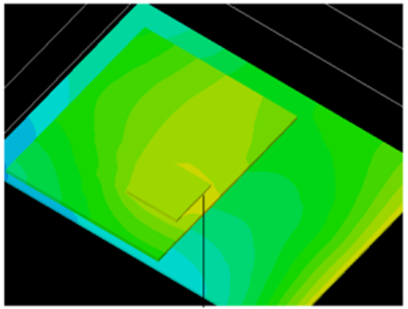
Schematic of simulated CPU module temperature and air flow distribution:
Ambient temperature: 40℃; Maximum temperature of the CPU chipset:64.43℃
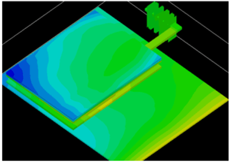
Schematic of the simulated temperature distribution on the top side of the RX module:
NO.
|
Maximum temperature
|
NO.
|
Maximum temperature
|
NO.
|
Maximum temperature
|
Source 1
|
59.43
|
Source 1.7
|
59.73
|
Source 3.1
|
59.59
|
Source 1.1
|
59.54
|
Source 2
|
60.02
|
Source 3.2
|
59.7
|
Source 1.2
|
59.66
|
Source 2.1
|
60.19
|
Source 3.3
|
59.77
|
Source 1.3
|
59.73
|
Source 2.2
|
60.16
|
Source 3.4
|
59.8
|
Source 1.4
|
59.76
|
Source 2.3
|
59.96
|
Source 3.5
|
59.8
|
Source 1.5
|
59.77
|
Source 2.4
|
59.76
|
Source 3.6
|
59.78
|
Source 1.6
|
59.76
|
Source 3
|
59.48
|
Source 3.7
|
59.74
|
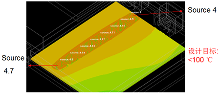
Schematic of the simulated temperature distribution on the bottom side of the RX module:
NO.
|
Maximum
|
NO.
|
Maximum
|
Source 4
|
60.83
|
Source 4.4
|
60.95
|
Source 4.1
|
60.53
|
Source 4.5
|
60.89
|
Source 4.2
|
60.92
|
Source 4.6
|
60.8
|
Source 4.3
|
60.96
|
Source 4.7
|
60.67
|
Fan operating point:
CPU fan: 2.43ft^3/min ,17.47Pa;
RX fan1: 2.23ft^3/min ,18.65Pa;
RX fan2: 2.5ft^3/min ,17.09Pa;
RX fan3:2.22ft^3/min,18.70Pa。
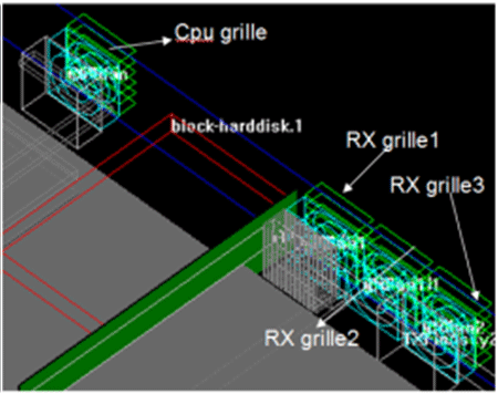
Air flow through fan grilles:
CPU grille:2.26ft^3/min;
RX grille1:1.95 ft^3/min;
RX grille2:2.23 ft^3/min;
RX grille3:1.962ft^3/min;
Total: 8.4ft^3/min。
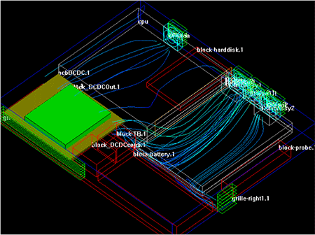
Miniature of the overall air flow trajectory from the simulation results:
Summary of the simulation results for the cooling solution:
|
CPU maximum temperature
(℃)
|
Temperature range of the heat source
(℃)
|
System air flow
(ft^3/min)
|
Simulation results of the solution
|
64.43
|
60.92~59.43
|
8.4
|
The results meet the requirements of CPUtemperature less than℃and heat source temperature less than 100℃ and the thermal design is complete.
|