Static VAR compensators are important equipment for regulating voltage surging and flicker, harmonics, and voltage imbalance. SVG is a more advance and new static VAR compensator and is an important constituent component of the flexible alternating current transmission system (FACTS) and the custom power (CP) technologies, which are the direction for the development of modern VAR compensators. Extensive applications of these two technologies can been found in the power transmission and distribution systems and these include long-distance power transmission, city secondary substation (35/110kV), vacuum consumable arc furnaces, and heavy industrial loads such as rolling mills and hoisters, photovoltaic power generation, wind farms, electric locomotive power supply, etc. A SVG is a device that emits a large amount of heat and it requires a heat sink with good cooling performance to ensure stable operations and a longer service life.
Winshare Thermal has abundant technical experiences in the SVC/SVG cooling. We supply solutions with superior cooling performance and these include the services and support for natural cooling, forced air cooling, and liquid cooling techniques.
The SVG cooling design requirements specified by the client are as follows:
|
Ambient temperature:
|
40?C
|
|
R4D560-AQ03-01
|
|
Elevation above sea level:
|
3000m
|
Environmental temperature requirement:
|
<35?C
|
|
Assuming the IGBT model number as:
|
Infineon IHV IGBT, 1250W/pcs with a total of 2pcs, resistor 100W����,total 2600W.
|
Thermal interface material model number:
|
0.2mm
K=4W/m*K
|
|
Power and the amount of modules:
|
A total of 7 pieces with a total power of 2600*7=18200W.
|
|
|
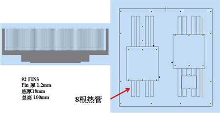
chematic of the layout of heat sources on a single SVG module with a heat sink:

Main parameters of the heat sink design proposed by Winshare Thermal:
- .? Heat sink dimensions 400x380x100mm which a custom heat pipe layout design;
- .? Thermal grease between the heat sources and the heat sink
- .? Use custom heat pipes with a 1.0mm wall thickness to ensure the cooling performance;
- .? Eight pieces of 9.5mm heat pipes embedded into the slots on the bottom surface and then pressed to ensure the cooling performance;
- .? Adjust the thermal conductivity of the epoxy to the corresponding data at the working temperature limit in the simulation so as to ensure the consistency between the simulation result and the real condition;
- .? Use all aluminum bonded heat sinks;
- .? Product gross weight is about 22.6 kg;
- .? Use Al5052 for the base plate and fins with a thermal conductivity of 138 w/m^2 K.
Parameters of the fans on the heat sink:
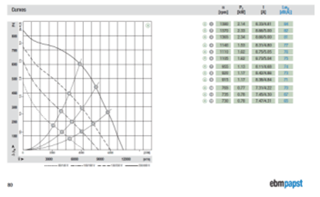
Ebm-papst 560 fan, model number: R4D560-AQ03; technical data is as follows:
Planar schematic of the heat sink profile:
heat sink with bonded fins and eight heat pipes:
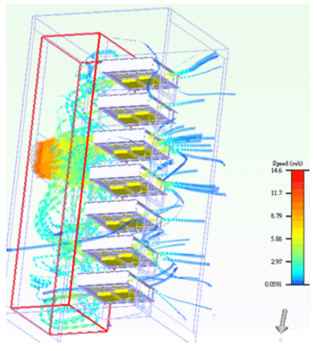
Schematic of the simulated air intake and exhaust:
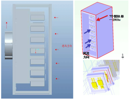
Schematic of air flow simulation results:
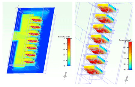
Schematic of heat temperature simulation results:
Schematic of simulation results of heat sink monitoring points:
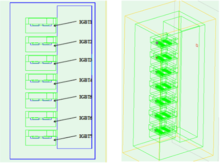
IGBT layout The intake air velocity at the external point which is 2~3cm to the middle point on the heat sink
Summary of simulation results:
|
Item
|
Maximum temperature ( C)
|
Intake air velocity m/s
|
Thermal resistance ( C/W)
|
The simulation results of the heat sink indicated that temperature of any point is below 75℃
and the temperature difference is smaller than35℃,so that the results meet custo.
|
|
Module 1
|
74.56
|
5.4
|
0.0133
|
|
Module 2
|
74.48
|
5.39
|
0.013
|
|
Module 3
|
74.52
|
5.4
|
0.013
|
|
Module 4
|
73.72
|
5.36
|
0.013
|
|
Module 5
|
74.56
|
5.56
|
0.013
|
|
Module 6
|
74.63
|
5.58
|
0.013
|
|
Module 7
|
74.43
|
5.58
|
0.013
|


