Variable-frequency drives (VFD) use variable frequency techniques andthe microelectronic technology to control the electric power control equipment of AC motors by a way of changing the working voltage and frequency of the motor. A VFD is composed of a rectifier (AC to DC), filter, inverter (DC to AC), activating unit, driving unit, detective unit, and micro-processing unit. The on/off of the IGBT inside a VFD is used to adjust the voltage and frequency of the output power. The required power voltage can be adjusted according to the motor's actual requirements so as to achieve the purpose of saving energy and adjusting speed.
VFD cooling is critical to the performance and service life of a VFD. It is no doubt that a good cooling for a VFD is essential, especially under the condition of fierce competitions since good cooling can enhance the quality of a VFD and enhance its competitiveness. For many years, Winshare Thermal has been providing various VFD manufacturers with advance cooling techniques and services. We supply tailor-made cooling solutions to our clients' VFDs along with effective technical supports on thermal simulation, thermal testing, etc. We safeguard the stability of the performanceof our VFD products.
Parameters:
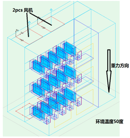
(1) Adjust the ambient temperature to 50?C;
(2) Use 2pcs of fans;
(3) Adjust heat sink structure and parameters.
(4) Use thermal grease 7762,K=4w/m*K,0.2mm
(5) Adjust the parameters of the heat pipe thermal model:
K radius=130W/m*K,
K length=32000W/m*K;
(6) Thermal contact resistance of the heat pipes isbonding 2.5E-6;
(7) Use Infineon IGBT thermal model.
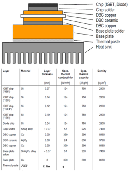
Schematic of simulation results and relevant parameters of IGBT model:
Below figure on the left is the figure of the InfineonFF600R17 internal structure and the schematic of heat-dissipating elements. The total power is 660W. We assume the thermal interface material as Thermal grease 7762 with a thickness of 0.2mm.
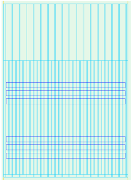
Schematic of simulation model relevant parameters of heat pipe heat sink:
Heat sink parameters:
Base dimensions:230*320*14mm;
Bonding fin: 15mm thick, 72mm high;
Shorter fin: length 210mm,offset 5mm,17fins;
Longer fins: length:320mm, 18fins;
Total 35fins
Heat pipe parameters:
D9.5 heat pipes:
Heat pipes are buried into the bottom of the cooling base plate by the buried-tube approach; 6pcs, pitch 12mm;
Epoxy bonding: K>=4W/m*K
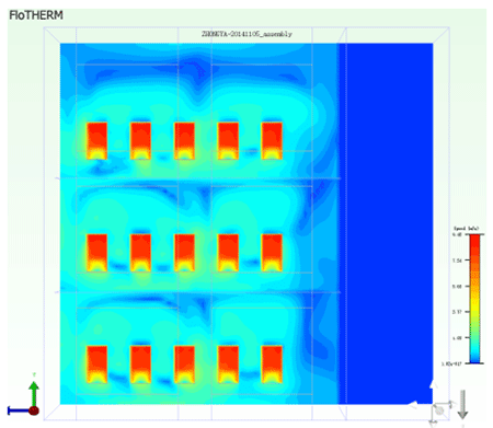
Schematic of simulation results of intake airflow velocity distribution profile for the module: module
module |
|
1 |
2 |
3 |
4 |
5 |
DP(Pa) |
209 |
211.6 |
208.3 |
210.5 |
211.1 |
Flow(M^3/H) |
693.4 |
694.9 |
692.4 |
699.0 |
703.1 |
|
6 |
7 |
8 |
9 |
10 |
DP(Pa) |
195 |
202.8 |
201.6 |
202.4 |
203.7 |
Flow(M^3/H) |
675.3 |
685.2 |
677.3 |
680.1 |
679.4 |
|
11 |
12 |
13 |
14 |
15 |
PD(Pa) |
195.3 |
199.7 |
197.1 |
200.2 |
200.5 |
Flow(M^3/H) |
671.6 |
680.6 |
669.5 |
673.6 |
674.5 |
Minimum air flow rate: 669.5m^3/H Maximum air flow rate: 703.1m^3/H
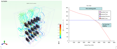
Schematic of thermal simulation results and fan operating points of the model of VFD module:
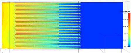
Schematic of simulation results of cross-sectional temperature distribution profile in the VFD heat sink (The module with the smallest flow rate for example):
(Minimum air flow rate: 669.5m^3/H, pressure: 197.1Pa)
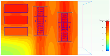
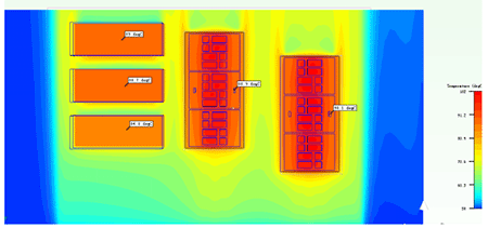
Schematic of simulation results of temperature distribution profile in the VFD module:
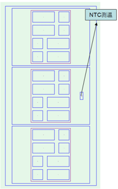
Schematic of simulation results of temperature distribution profile in IGBT NTC and diodes:
|
H.S
Max Temp
|
H.S Max DT
|
Diode case temp
(?C)
|
Maximum node temperature of
IGBT internal core device (?C)
|
Max Junction Temp.
|
NTC temp.
#1
|
NTC temp.
#2
|
NTC DT
|
#1
|
#2
|
H.S. with H.P.
|
91.6
|
41.6
|
89
88.7
84.8
|
88.9
|
90.1
|
1.2
|
107.7
|
108.9
|
Ambient temperature: 50?C; assuming Thermal grease 7762 with a thickness of 0.2mm.
|